Project - Open Door Sensors
This was my first sensor project. The sensors themselves were simple, but I had to learn how to manage the sensors with an Arduino (also simple) and how to incorporate them into an XBee mesh network. As noted elsewhere on this site, the book "Building Wireless Sensor Networks" by Robert Faludi was my bible as I started to experiment.
The Sensors
The sensors used in this project are magnetic reed switches made by Black & Decker. The part number on the switch is 180424 and the part number on the magnet is 180087. Back in the 1990's I came into possession of a small Black & Decker Home Security System and these magnetic reed switches were part of the package. I could find neither the switch nor the magnet on the internet this morning, but there are hundreds of magnetic reed switches available. A picture of my sensor is below.
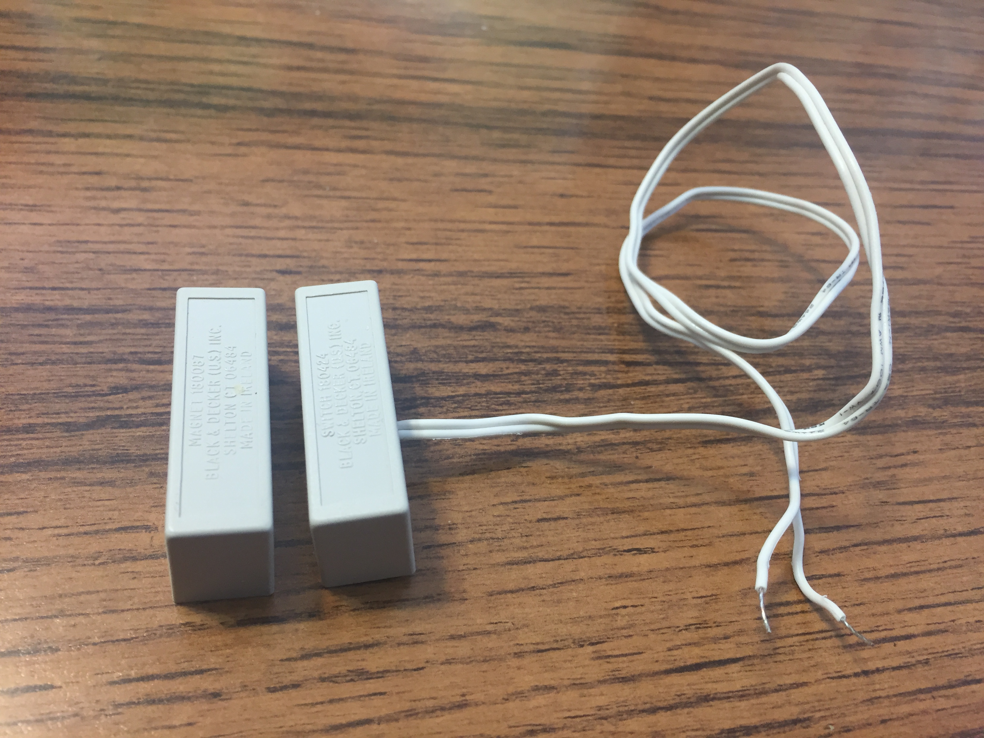
This is a "normally open" switch. In the absence of the magnet, the switch is open and no current flows. The Arduino input pin is pulled low and the Arduino interprets this state as "door is open". When the magnet is near the switch, the reed is pulled closed and current is allowed to flow. The Arduino input pin is pulled high and the Arduino interprets this state as "the door is closed".
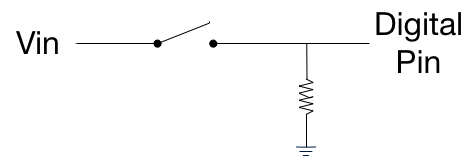
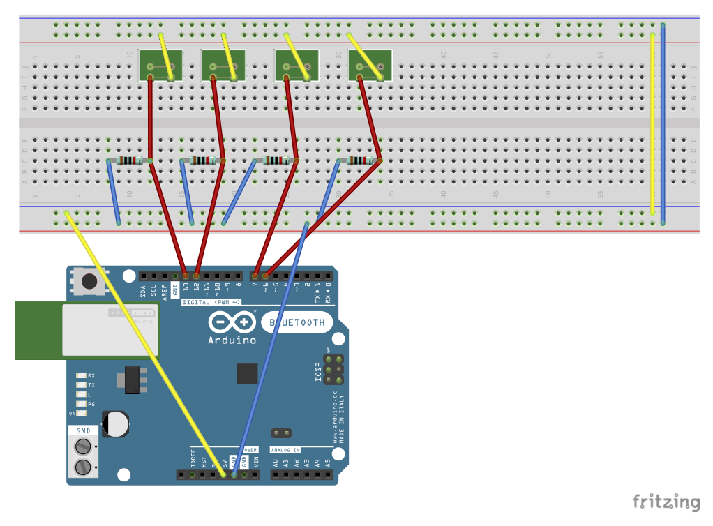
The only complication is that the Arduino input pin must be connected to ground through a 10k ohm resistor to assure that it is actually pulled low when current is interruped. This little diagram shows this.
The Sensor Assembly
No further assembly was needed for this sensor. Out of the box, the sensor is ready for installation. The following picture shows the door open sensor installed at the author's basement door.
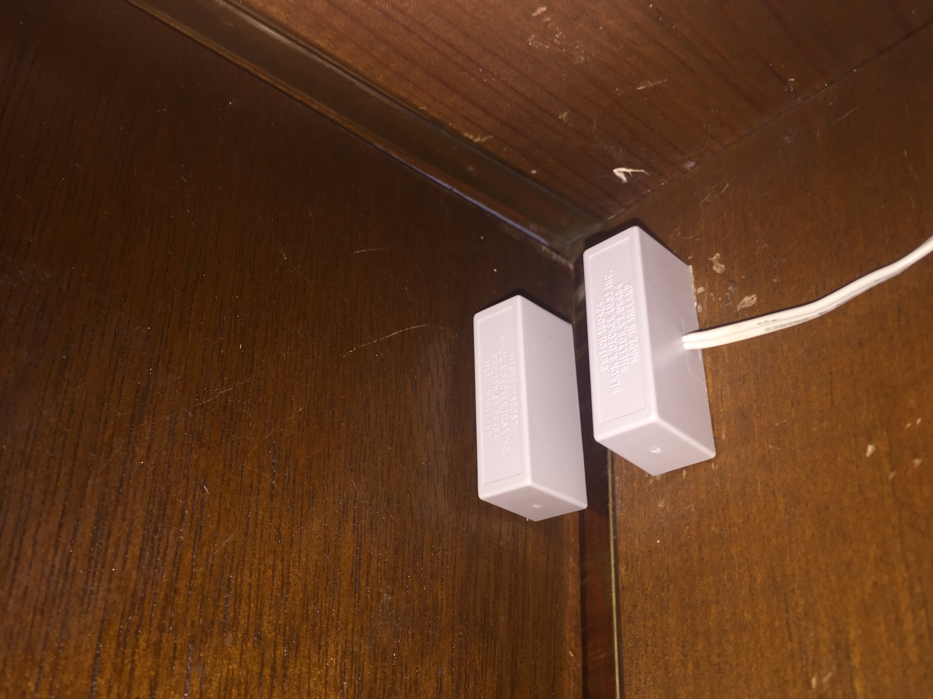
The switch is attached to the frame and the magnet is attached to the door. Alignment is only moderately important but when the door is closed the magnet must be close enough to the switch (or strong enough) to pull the switch closed.
The Electronics
No documentation of an "electronics project" is complete without schematics and I don't intend to violate that principle. But first, some general notes:
I was introduced to the concept of "Arduino shields" as I read about other people's XBee / Arduino projects. I quickly decided that using an XBee shield was a good way to implement my Open Door Sensor project. But sure enough, there was a "gotcha." There wasn't near enough room on an XBee shield for all of the electronics I envisioned. What to do? What to do?
After some thought, the solution was obvious. I would sandwich another shield (a ProtoShield) between the Arduino and the XBee shield. The physical hurdle was to assure that the headers could be stacked high enough to clear the stuff on the middle board. The electronic hurdle was to assure that I didn't draw more current than the Arduino provided.
In considering what should go on each layer of the sandwich I decided that I would group the "input" electronics on the middle board, the ProtoShield. That would leave the "output" electronics to go on the top board, the XBee Shield.
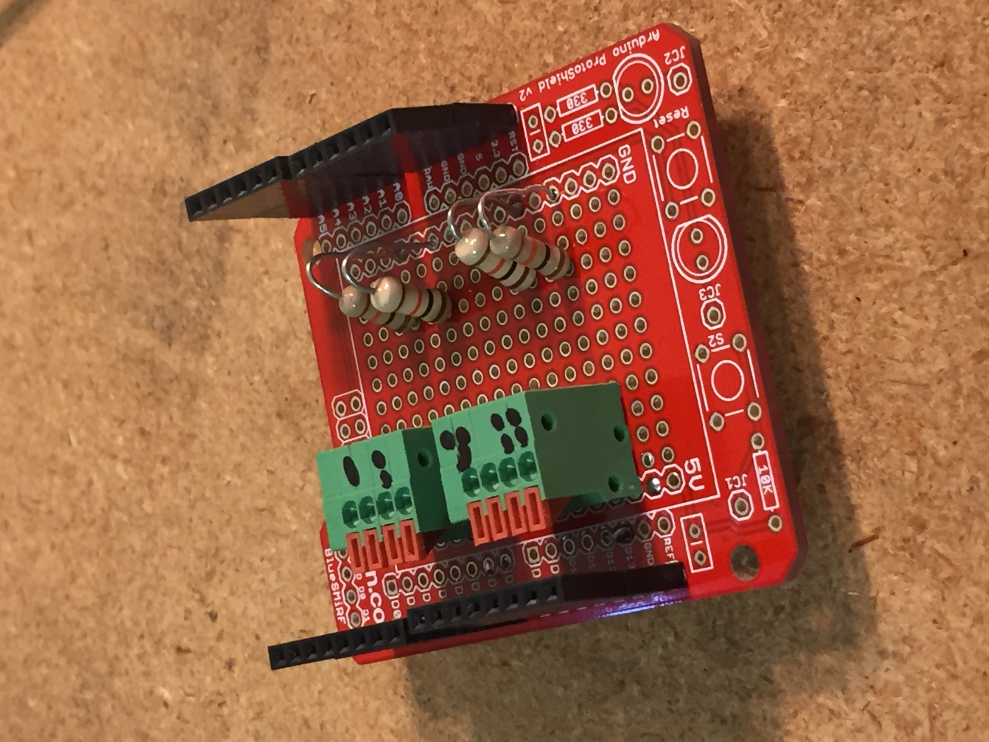
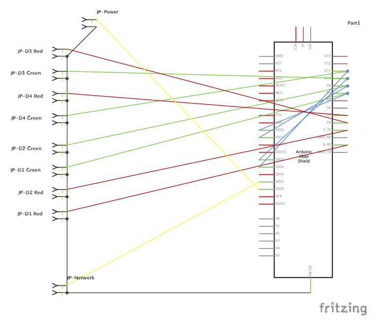
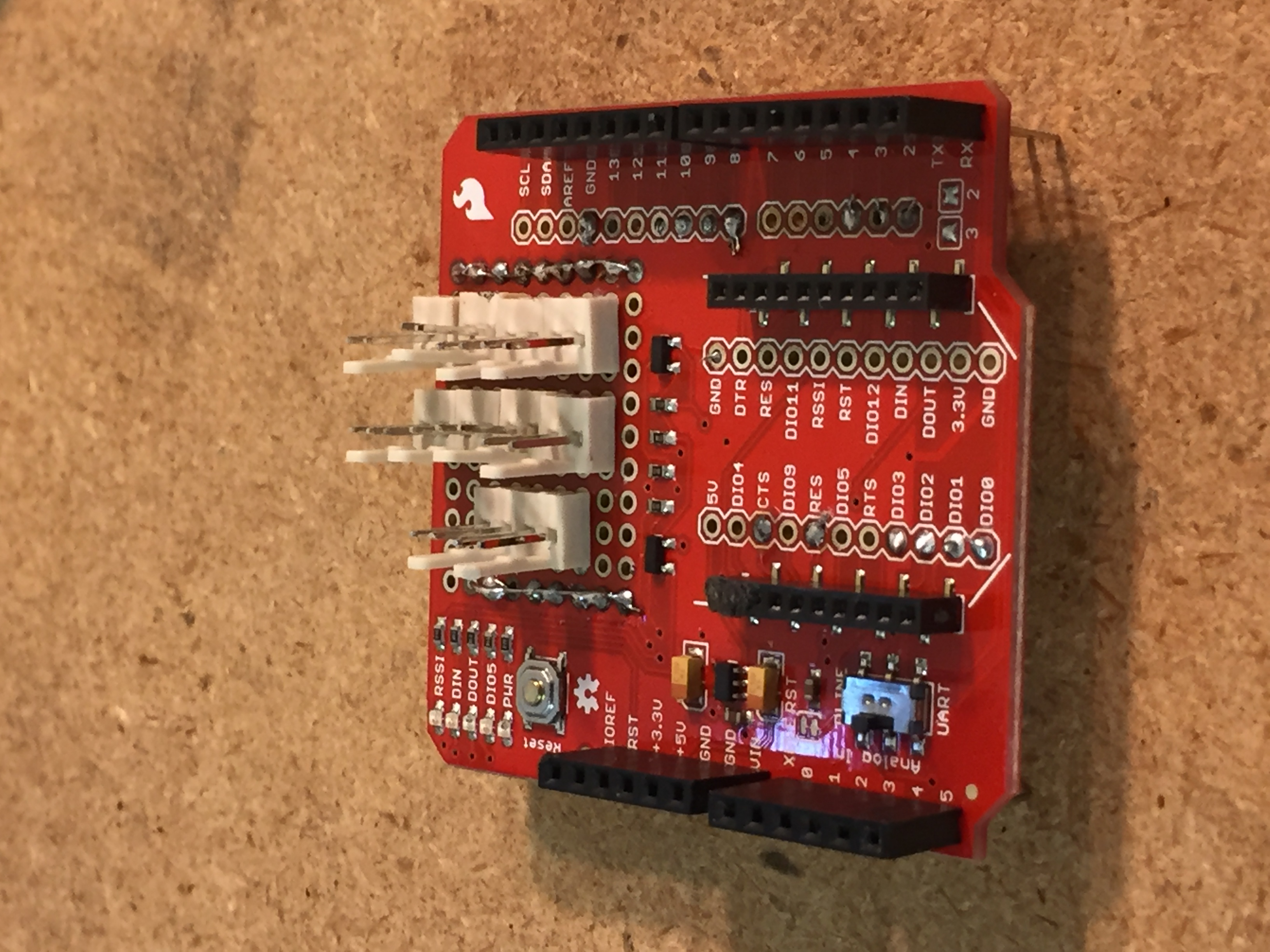
This picture shows my initial XBee / Arduino sandwich (without the XBee) and the paragraphs below describe the two layers in detail (and provide schematics).
The Input Board
The input electronics consisted of some spring terminals (to connect the Arduino to the outside world) and the pull-down resistors discussed earlier.
The ProtoShield was sourced from SparkFun Electronics. The part number I used was DEV‑11665. SparkFun has since revised their shield and the current part number is DEV‑13819. The headers are tall stackable headers and each bank has two layers. The spring connectors and resistors are generic.
The Output Board
The output electronics consisted of a set of ten polarized connector pins (for LEDs) and all the wiring needed for the Arduino to communicate with the XBee and the connector pins. I had a red LED and a green LED for each sensor. I also connected one LED to the XBee's "power-on" pin and one to the XBee's "associated" pin.
The XBee Shield was sourced from SparkFun Electronics and the current part number is WRL-12847. The headers are tall stackable headers. The polarized connectors were also sourced from Sparkfun. The part number for the header is PRT-08233. The part number for the female house is PRT-08095 and the part number for the crimp pins is PRT-08100.
I had a lot of trouble with these connectors. The male headers had to be glued to the board before I soldered and the through-hole pin seemed short when working on the back side of the board. I also had trouble crimping the pins to the connecting cable. I think the later was my lack of experience working with crimped pins.
The finished project was extremely touchy. LEDs would quit working when the module was moved and then start working again when moved again... Argh! After about six months, I'd had enough and I rebuilt the entire Output Board. I replaced the polarized pin connectors with JST connectors (SparkFun PRT-09915). I gave the red LED and the green LED for each sensor a common ground and thus reduced each four wire connection to a three wire connection. Finally, I replaced the LED assemblies with LEDs from SparkFun that have built-in resistors. The green part number is COM-14563 and the red LED part number is COM-14560. The reliability of my project has soared.
Mechanical Notes
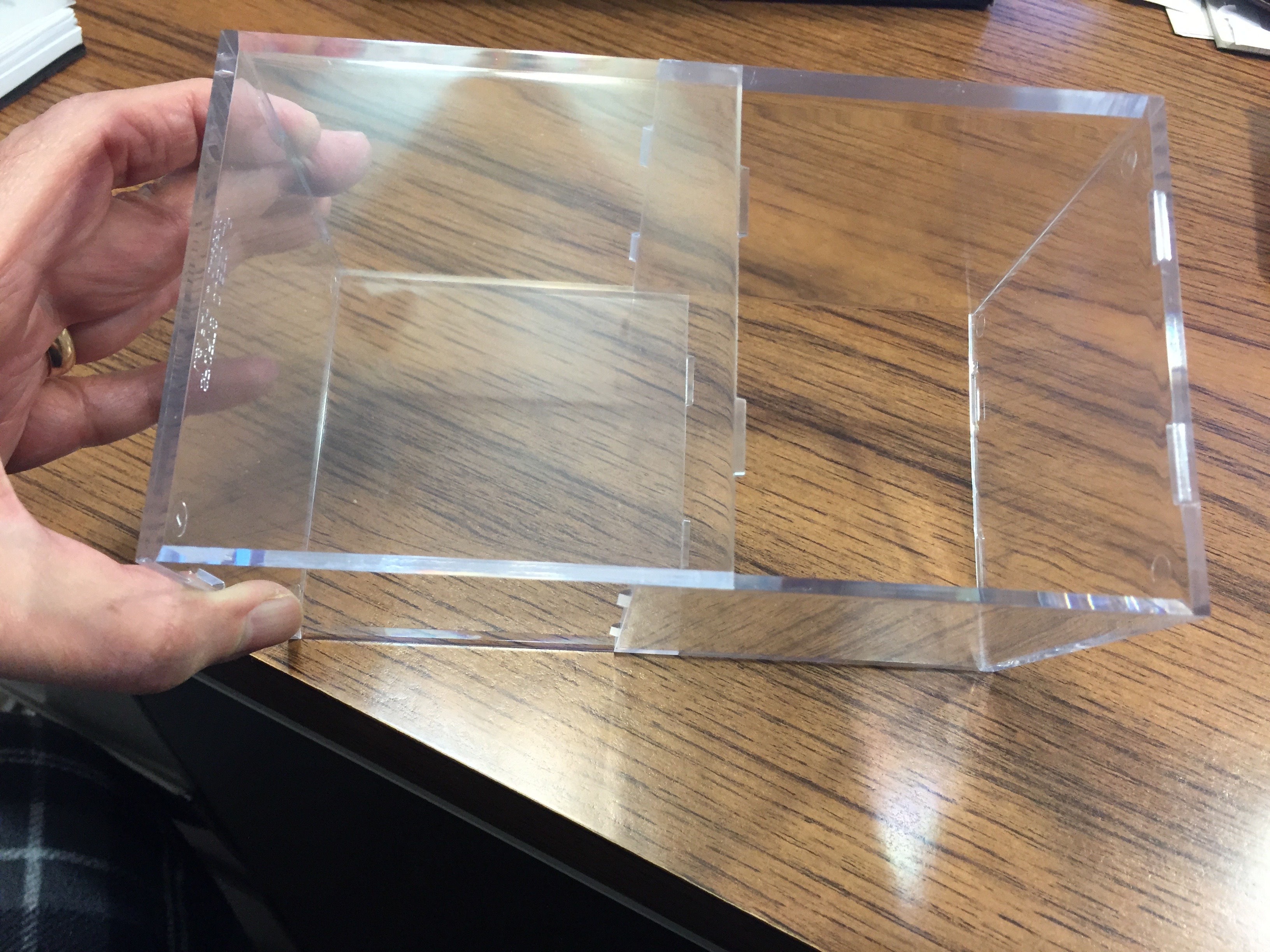
The biggest challenge in the mechanical design of this project was finding a "box" to house it. I had to avoid a metal box because metal would attenuate the radio inside. And a box had to be the right size. I could find boxes with adequate length and width, but they were never deep enough. And when I found boxes that WERE deep enough, the length and width were far, far more than I needed. All of this because of my three layer sandwich.

The solution came when I discovered softball display cubes. They were the perfect size, a cube.
I sourced softball display cubes at the Container Store in Edina, MN.
The plastic (acrylic) was difficult to work with. I had to drill holes for the LED holders and I had to cut slots for access to the power jack and USB port. The plastic melts and cracks and scratches. One has to protect the plastic and be very, very patient when machining it. Subsequent project boxes are much cleaner than this initial one.
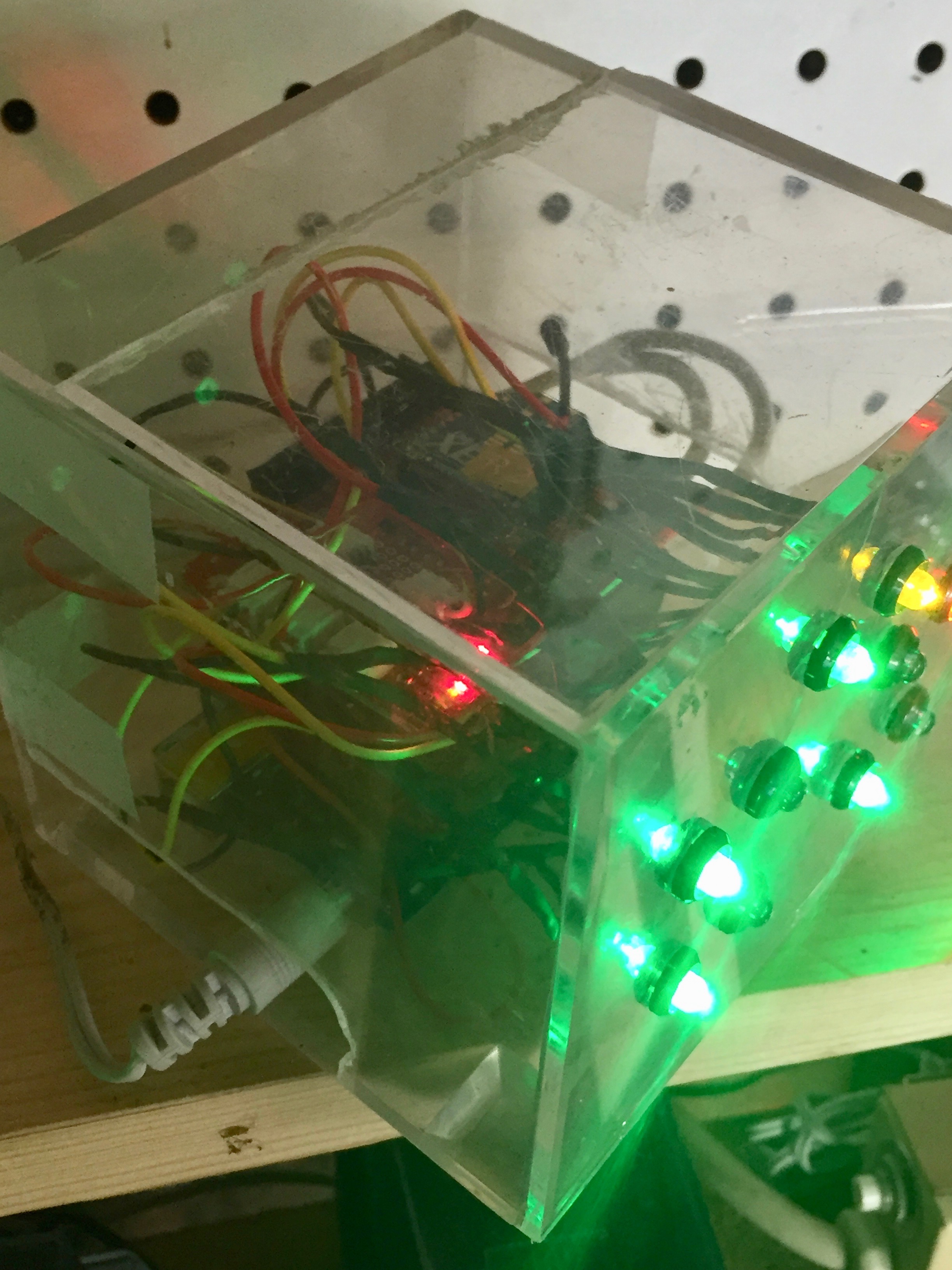
This is the Open Door Sensor project installed "in the wild." If you look closely, you can see the JST connectors that replaced the initial polarized connectors on the top board.
Software Highlights
This section is intended to highlight unusual aspects of the Arduino software. The Processing-based software running on my iMac to display the status of the Open Door Sensors is described elsewhere.
Most of the Arduino code for this project was straight-forward... except:
I had read about "reliably detecting the closing of a switch" in the Arduino Cookbook by Michael Margolis. The goal is to avoid false readings caused by contact bounce. Contact bounce happens at the split second the switch contacts open or close. The spurious signals produced would cause the LEDs in this project to flicker.
The process of eliminating spurious readings is called "debouncing. " A debounce function is called in the Arduino sketch with the pin number of the switch I want to debounce. The function returns true if the switch is closed and stable. I've never had a problem with flickering LEDs and I credit inclusion of this "debouncing" function.
Code for the debounce function can be found on page 143 of the Arduino Cookbook.
Open Issues
None... After I solved the reliability problems by rebuilding the Output Board and replacing the polarized connectors, this project works the way I want.
