Project - Temperature Sensors
Parts List
The objective of this project was to add some temperature sensors to my mesh network. I wanted to measure temperature inside the garage and on the patio. As with the light sensors, the temperature sensors would send analog signals to a central Arduino / XBee module. Then things change a bit from my previous projects. The Arduino would calculate temperatures from the analog voltages and then construct a single text message that it would pass along to the XBee. The XBee would then broadcast the text message as a data packet on the mesh network. My challenge was learning to use the new XBee frame type... both constructing the data packet before transmission and interpreting the data packet when the transmission was received.
The Sensor
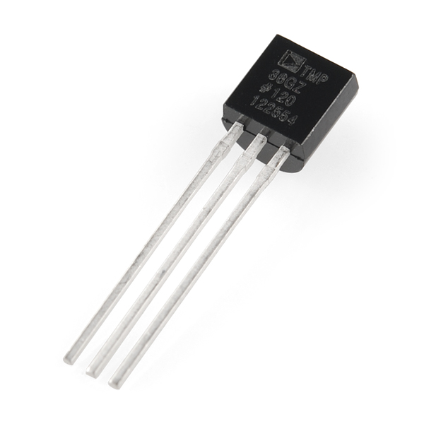
The sensors used in this project are the TMP36 Low Voltage Temperature Sensors produced by Analog Devices (pictured). I sourced these sensors from Sparkfun Electronics. The SF part number is SEN‑10988. They are about $1.50 apiece.
The Sensor Assembly - Theory
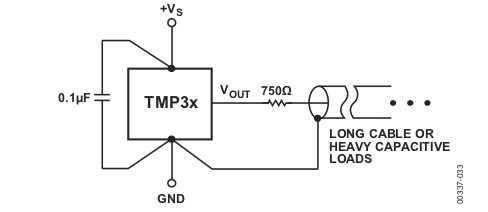
At the recommendation of the sensor manufacturer, the bulk of this project's input electronics is distributed to the sensor assembly itself. The schematic below comes from the TMP36 datasheet and shows a capacitor and a resistor in an assembly with the sensor. The datasheet provides this explanation for the capacitor:
Note the 0.1 μF bypass capacitor on the input. This capacitor should be a ceramic type, have very short leads, and be located as close as possible in physical proximity to the temperature sensor supply pin. Because these temperature sensors operate on very little supply current and may be exposed to very hostile electrical environments, it is important to minimize the effects of radio frequency interference (RFI) on these devices.
The datasheet offers this explanation for the resistor:
Although the TMP3x family of temperature sensors can drive capacitive loads up to 10,000 pF without oscillation, output voltage transient response times can be improved by using a small resistor in series with the output of the temperature sensor. As an added benefit, this resistor forms a low-pass filter with the cable capacitance, which helps to reduce bandwidth noise
The Sensor Assembly - Practice
I intended to install one sensor assemby "outdoors", on the patio. SO, I needed to make the sensor assembly waterproof. In surfing the 'net, I came across an "Instructable" for building a waterproof sensor: exactly what I envisioned.
The username on the Instructable is "solarmax" and here is the link to the article. I shamelessly adopted the ideas presented in this project for my own sensor assemblies.
The sensor is soldered to Cat5 cable just as described in the "Instructable". The only change I made was to also solder a 0.1μF ceramic capacitor to the sensor leads. It was difficult to keep everything electrically isolated as I soldered the sensor leads. I actually used pieces of electrical tape in places where shrink tubing didn't work.
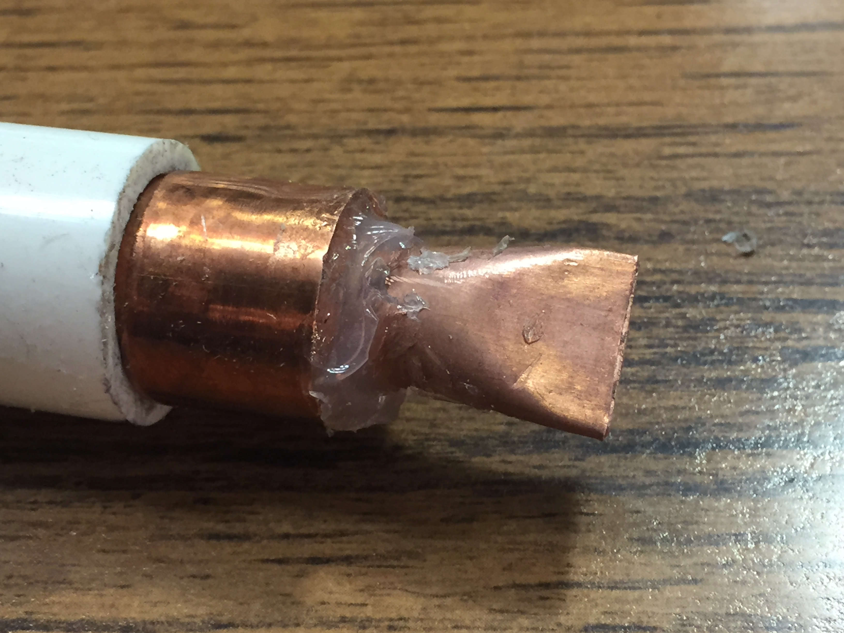
The sensor with its soldered tail was then "shoved" into a piece of 1/4" copper pipe. The end of the copper pipe was crimped closed as shown in this picture.
I dabbed the sensor with thermal paste before inserting it into the crimped pipe. This had been recommended in comments to the "Instructable" article. It alledgedly would improve sensor response.
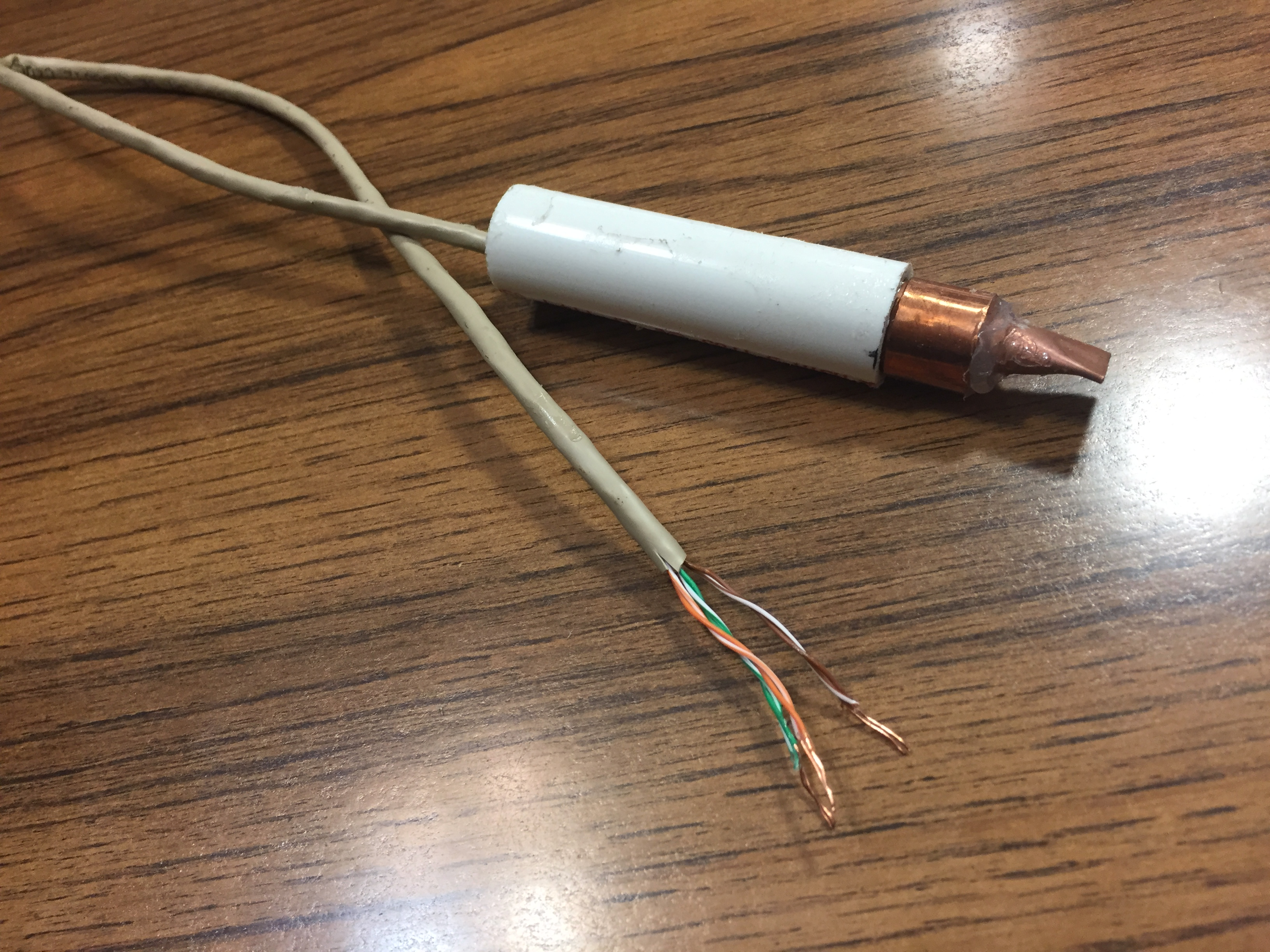
The whole assembly was then assembled. This picture shows the size of the finished product. The PVC piece is about 6" in length.
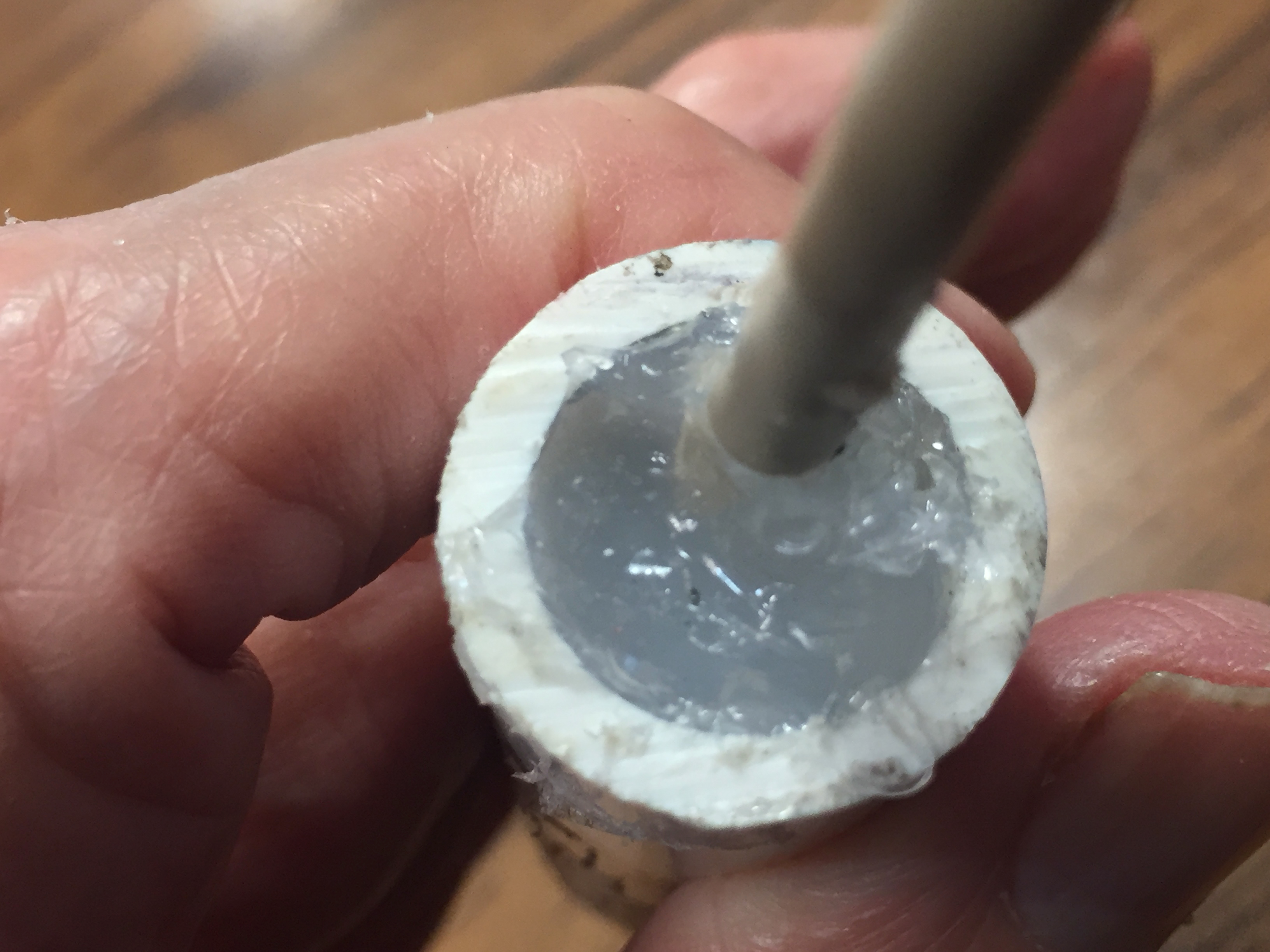
Waterproofing was achieved by filling everything with DAP 100% Silicon Aquarium Sealant. A difficulty with this approach is that one can't SEE if the PVC pipe is filled with sealant. One has to just keep squishing it in until it no longer squishes in. Note that the 1/4" copper pipe was filled with silicon sealant before attachment to the 1/2" copper cap.
This picture shows the PVC filled with silicon sealant.
The Electronics
At a macro level, the electronics for this project continued to use the design philosophy developed in earlier projects. I retained the idea of a three-level Arduino / ProtoShield / XBee Shield sandwich. I also kept the idea of isolating Input electronics on the ProtoShield from Output electronics on the XBee Shield. The following paragraphs highlight lower level similarities and changes.
The Input Board
With the components needed for the input circuitry distributed to the sensor assemblies themselves, there were NO components left to occupy the Input Board. The schematic shows the simplicity of the situation. The only challenge was to assure that the right sensor input line was connected to the right Arduino input pin.
The Input Board (cont'd)
This picture shows the completed Temp Sensor Input Board. There were two changes of note from earlier projects:
First, SparkFun revised the layout of their Arduino ProtoShield. The new part number is DEV-13819. The functionality I have used is unchanged. The little board connected with tabs in front of the headers will be snapped off before the project is installed in its box.
The second change (from the last project) is that I did not create a common ground for the sensor cables "outside" of the project box. The new SparkFun ProtoShield provides a pre-wired ground bus so it was just easier in this case to bring the ground wire for each sensor inside the project box. (As you can see in the picture, the new ProtoShield layout also has a pre-wired 5v bus... handy.)
After this picture was taken, I used my hot glue gun to physically tack the input tail to the ProtoShield. This provides some strain relief for the solder connections. I had a broken solder connection on the input board of the Light Sensor project which a dab of glue would have prevented... The little things you learn as you go.
The Output Board
The Output Board for this project again underwent a major changes from previous projects. The biggest change is that there is no longer an array of connectors for red and green LEDs to fit onto the board. The output function of the LEDs was largely replaced with a simple LCD screen and the LCD only requires one three-wire cable.
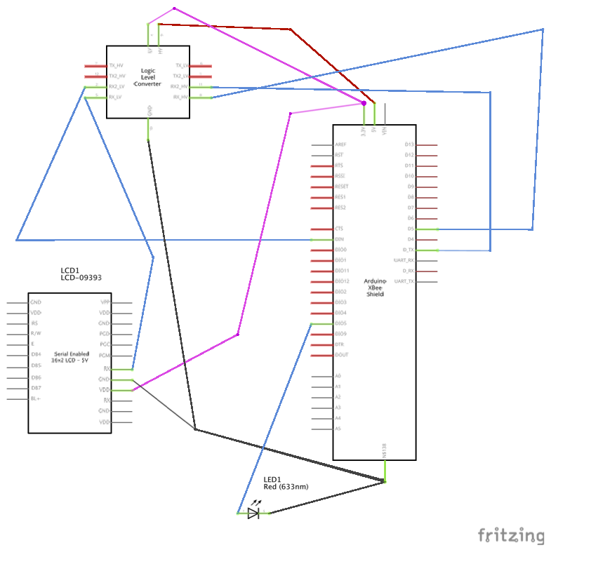
This is the schematic for the Temp Sensor Output Board. The sole LED is connected to the XBee's Associated pin. It has an embedded resistor. I decided that also having an LED connected to the XBee's Power On pin was redundant so I eliminated it. Simplicity.
I retained the concept of using a Logic Level Converter between the 5v Arduino and the 3.3v components. The Arduino outputs 5v signals. Both the LCD and the XBee require 3.3v input signals. The schematic shows how every signal between the Arduino and the 3.3v components is routed through the Logic Level Converter.
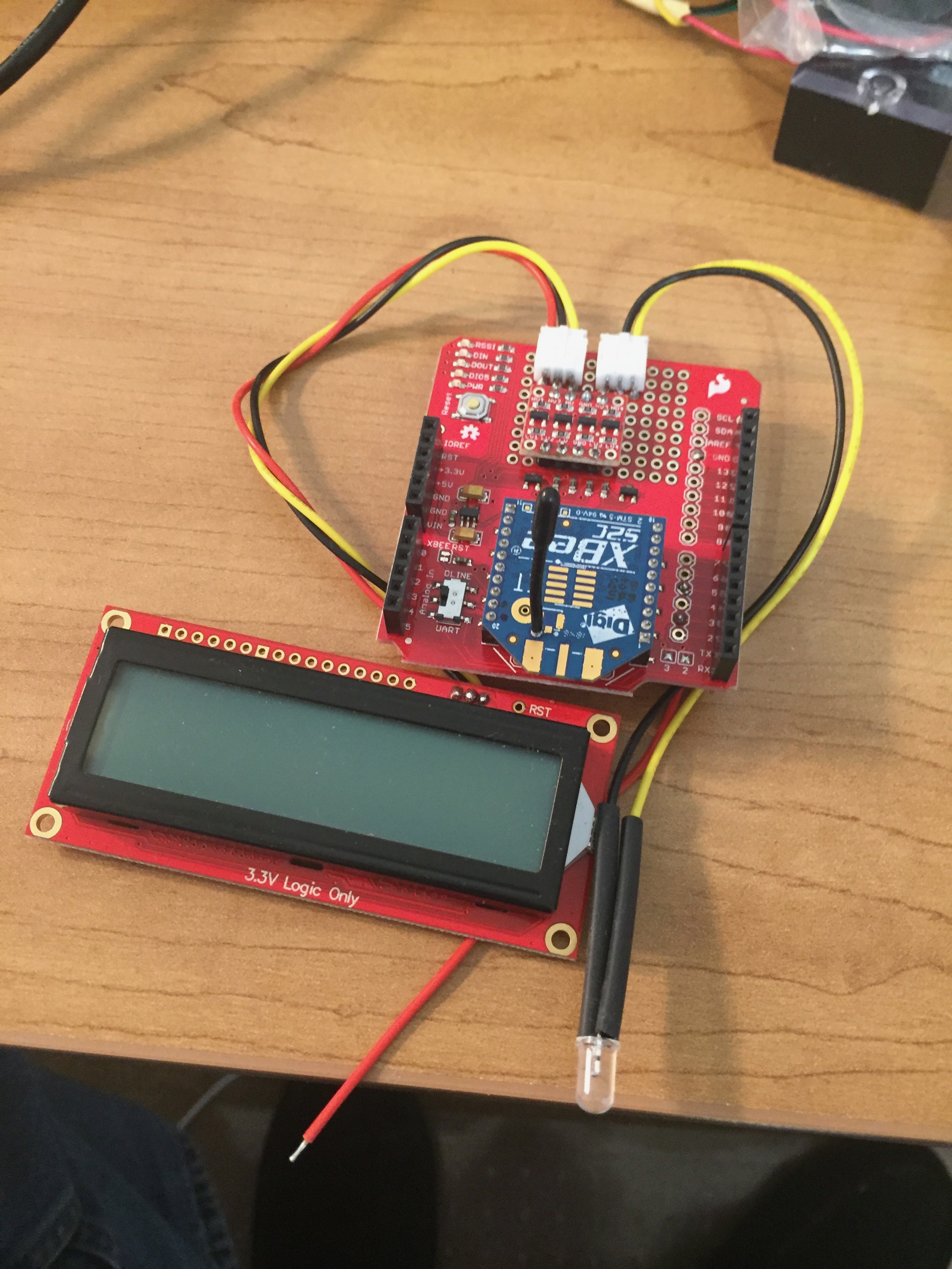
This picture shows the completed Temp Sensor Output Board with its LED and LCD screen. The XBee Shield was sourced from SparkFun Electronics and the part number is WRL-12847. The Logic Level Converter was also sourced from SparkFun and its part number is BOB-12009. Finally, the LCD was sourced from SparkFun and its part number was LCD-14072. The LCD was a 16x2 Black on RGB serial LCD. This particular model has been retired. Its replacement is part number LCD-16396.
Mechanical Notes
Pictured is the completed Temp Sensor Ardino / XBee sandwich installed in the project box. A softball display cube was again used as the project box. This time it was a FIASCO!
I did not have to drill umpteen holes for LEDs as I had in previous projects, but I did have to cut a rectangular hole for the LCD. I bought a special tool (an electric knife) to help make this as easy as possible. It didn't help much.
My first attempt resulted in a slightly slanted rectangular hole. I decided I could live with that. When I filed down the rough spots in the rectangular hole, I created cracks inside the edges of the front panel. I decided I could also live with that. But because the rectangular hole was slanted, the holes needed to attach the LCD were misaligned. I couldn't live with that. I started over with a new cube.
The rectangular hole in the second cube was straight, but still a little ragged. At least the LCD fit and the four holes needed to attach the LCD lined up appropriately. I was on a roll. And then I drilled the hole for the single LED. BAM! The bit grabbed and cracked the plastic. I decided I could live with that, but I would need to do something to structurally strengthen the plastic in front.
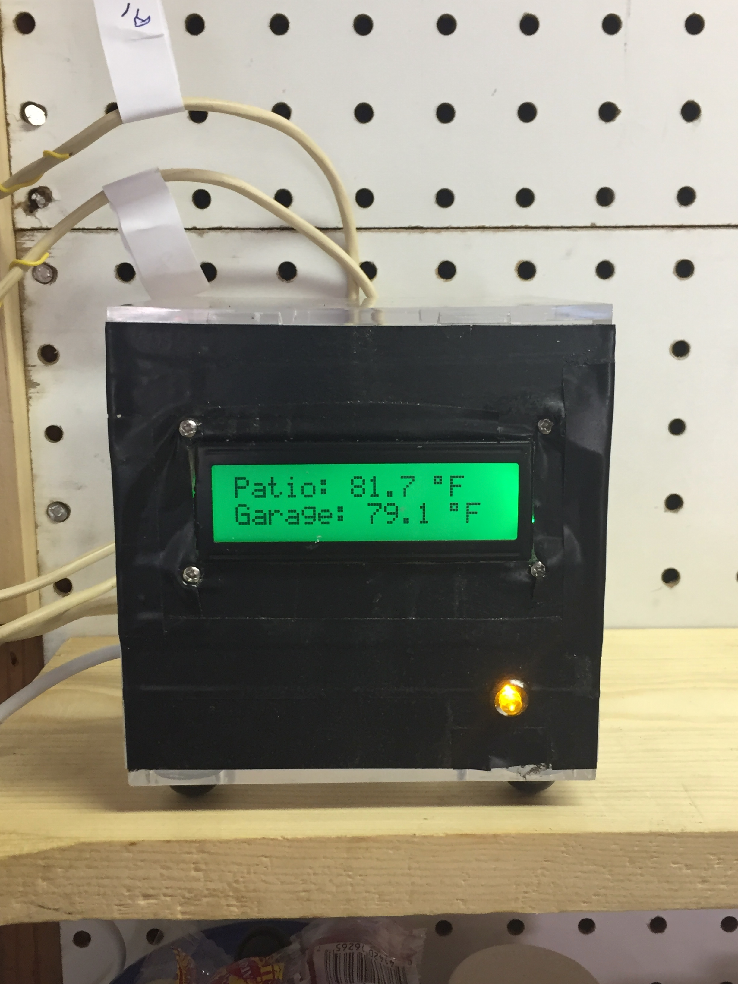
As shown in this picture, I covered the faceplate side of the cube with black electrician's tape. With the tape, I could hide the ragged edge of the LCD hole and strengthen the cracked plastic around the LED hole. Plus I thought it would look cool. It kinda does <g>.
I think I will search for a different project box before kicking off my next project. These plastic cubes are just too hard to work with.
Software Notes
This section is intended to highlight unusual aspects of the Arduino software. The Processing-based software running on my iMac to display the status of all my sensors is described elsewhere. There are three items of interest in this project's Arduino sketch.
The first item of interest is the code that converts the analog voltage received from a TMP36 sensor into a meaningful temperature value. Here 'tis. The comments embedded in the code explain what happens in each line.
// Convert raw sensor reading to millivolts.
// Arduino's ADC resolution is 0-1023
// Sketch assumes reference voltage is 5v (5000 mV)
milliVolts = (float(rawSensorReading) / 1024) * 5000;
// Convert milliVolts to ºC
// Again: The relationship is 10 mV / degree centigrade
// with a 500 mV offset to allow for negative temps.
temperatureC=(milliVolts - 500)/10;
// Convert ºC to ºF with familiar formula
temperatureF = (temperatureC * 9.0 / 5.0) + 32;
The second item of interest in this project's Arduino sketch is the code that constructs and sends the data payload to the XBee.
In previous projects, Arduino processing rendered a binary (open/shut, on/off) decision for each sensor reading. That binary result was then sent to a pre‑assigned "input pin" on the project's XBee. Each sensor was assigned a different XBee pin and the assigned pins were configured as "digital" input pins. After receiving the signal from the Arduino the XBee would construct and transmit its message. In XBee‑speak, the XBee would construct and transmit a 0x92 frame type. The receiving software would know from whence data came through a combination of the XBee ID and pin number included in the 0x92 frame. Note that NO special code was needed in the Arduino sketch to construct the data payload for the XBee transmission.
In THIS project, that has all changed.
As shown in the code above, the Arduino in this project renders a floating-point value result, rather than a binary decision, after processing sensor input. Consequently. the mechanism for constructing and transmitting that result had to be different from what I had used before. After doing some research and looking for options, I decided that I would construct a simple text message for the XBee to broadcast that would include a "sensor ID" paired with the associated temperature value. Moreover, I decided that I would aggregate readings from all (both) of the sensors into one transmission and let the receiving software parse the message back into pairs of "sensor IDs" and temperature values.
In XBee-speak again, the Arduino would construct a 0x90 XBee frame type and send it to the XBee's general purpose Tx pin. Fortunately, through the magic of Andrew Rapp (see my Home Page), there is a library for the Arduino IDE that facilitates Arduino/XBee communication. The only real challenge was to use the right "kind" of string in each statement. Here is the code that constructs and sends the 0x90 XBee frame:
// Payload for XBee->XBee transmit frame
// This allows for different sized temperatureFStrings
uint8_t
myXBeeDataPayload[myCombinedXBeeDataStringLength+1];
// Plus 1 because I have to get the null termination
myCombinedXBeeDataString.
getBytes(myXBeeDataPayload,
myCombinedXBeeDataStringLength+1);
//The ZBTxRequest object constructs the 0x90 packet
ZBTxRequest myZBTxRequest =
ZBTxRequest(myXBeeAddress64, myXBeeDataPayload,
sizeof(myXBeeDataPayload));
//The .send command sends the packet to the XBee's Tx pin
myXBee.send(myZBTxRequest);
The data payload in the transmitted 0x90 XBee frame looks like this: S1->68.2F/S2->68.4F
The third item of interest in this project's Arduino sketch is a software solution to a hardware limitation. The Arduino Uno (the Arduino model I'm using) only has one hardware serial port. This port communicates on the Arduino's digital pins 0(Rx) and 1(Tx) as well as with a computer via USB. It is handy for debugging and also for controlling the Arduino from a keyboard. But, it's not enough. I needed three serial ports.
I wanted to retain the hardware serial port that communicates with a computer via USB. It has proven to be invaluable in debugging my Arduino sketches. I also needed a serial port for the Arduino to communicate with the XBee. The Arduino constructs and sends the 0x90 data frame to the XBee through a serial port. Finally, I needed a serial port for the Arduino to communicate with the LCD screen. What to do ? ? ?
The solution was surprisingly easy. A gentleman named Mikal Hart has developed an Arduino library to allow serial communication on other digital pins of the Arduino, using software to replicate the functionality. The library is called SoftwareSerial. Here's the code that implements the extra serial ports:
First declare and initialize the variables;
// I reserve pins 0(Rx) & 1(Tx) for the UART/USB connection to iMac
// This 2nd serial port (for this Arduino) is for the XBee
// Rx of Arduino to Rx of XBee. Tx of Arduino to Tx of XBee.
const byte myXBeeRxPin = 2;
const byte myXBeeTxPin = 3;
SoftwareSerial myXBeeSerial(myXBeeRxPin,myXBeeTxPin);
// This 3rd serial port (for this Arduino) is for the LCD screen
const byte myLCDRxPin = 4;
const byte myLCDTxPin = 5;
SoftwareSerial myLCDSerial(myLCDRxPin,myLCDTxPin);
Then inside the sketch's setup() code:
// The default UART/USB port for the Serial Monitor
Serial.begin(9600);
// The port Arduino -> XBee
myXBeeSerial.begin(9600);
// The port Arduino -> LCD
myLCDSerial.begin(9600);
// This code tells the XBee object which serial port to use
myXBee.setSerial(myXBeeSerial);
Finally, just use the Arduino's vanilla serial commands.
Be careful to reference the correct serial port. For example:
myLCDSerial.write(254); OR
Serial.print("Sensor ID‑> ");
Open Issues
At this point the issues the only open issue I have is with the stability of the sensor readings. The displayed temperatures can change by a degree or two every few seconds as you sit and watch them. I don't like that. You KNOW that the temperatures aren't changing that fast.
From what I've read, the sensors themselves are VERY stable. But, they are also VERY sensitive to voltage (Vref) variations. And I didn't design any fancy circuitry to assure a stable voltage "at the sensor". So, I'm stuck with the bouncy readings.
But, also from what I've read, I could add an algoritm to my Arduino software to smooth the sensor readings before they are displayed. For example I could capture three consecutive readings (maybe 5 milliseconds apart) and then average them before displaying the result. Interesting. I will continue to research software solutions for this issue. This is my first project using the ADC capability of the Arduino.
