Project - Light Sensors
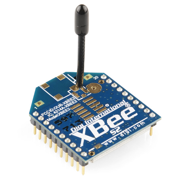
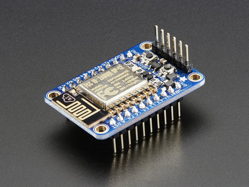
The objective of my 2nd project was to monitor the "on / off" status of lights around the garage. Three photocells would "sense" the level of light emitted by three different light fixtures and send analog voltage signals to a central Arduino / XBee module. The Arduino would convert the analog signals to digital "on / off" signals and send tthem to the XBee. The XBee then would broadcast the result on the mesh network. So simple in theory...
The Sensor
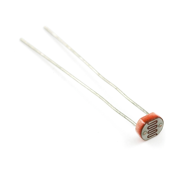
The sensors used in this project are CdS Photo conductive Cells (pictured). I sourced these sensors from Sparkfun Electronics. The SF part number is SEN‑09088. These sensors are about $1.50 apiece.
The Sensor Assembly
Before deploying this sensor, I needed to add a longer "tail" to the two leads. I also needed to mount the sensor in a container that offered some dust and dirt protection and that could be "pointed" at a light source. In surfing the 'net for DIY sensor projects, I had come across a gentleman named Andrew Oke who mounted a temp sensor in a plastic BIC pen case. The link to his video is here. I adopted his ideas.
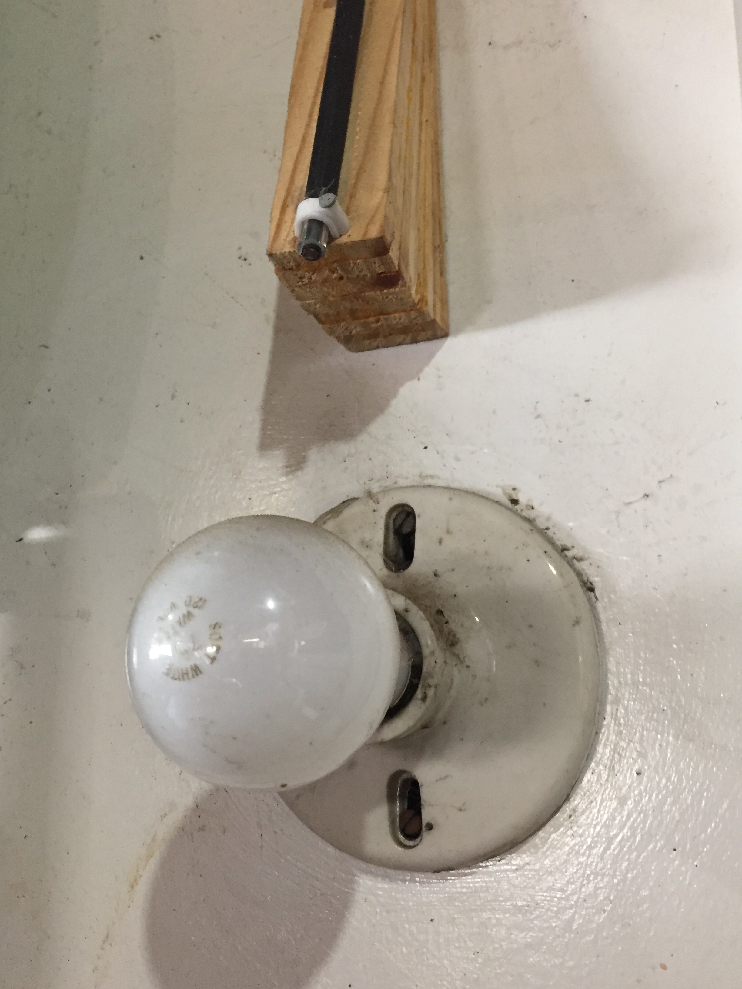
This is a picture of a completed Light Sensor Assembly installed "in the wild". The plastic pen tube containing the sensor is mounted on a ramp of wooden shims. There is a lot of ambient light in the garage, particularly with the garage door open and particularly in the summer. The Light Sensor Assembly had to be mounted to point directly at the light source.
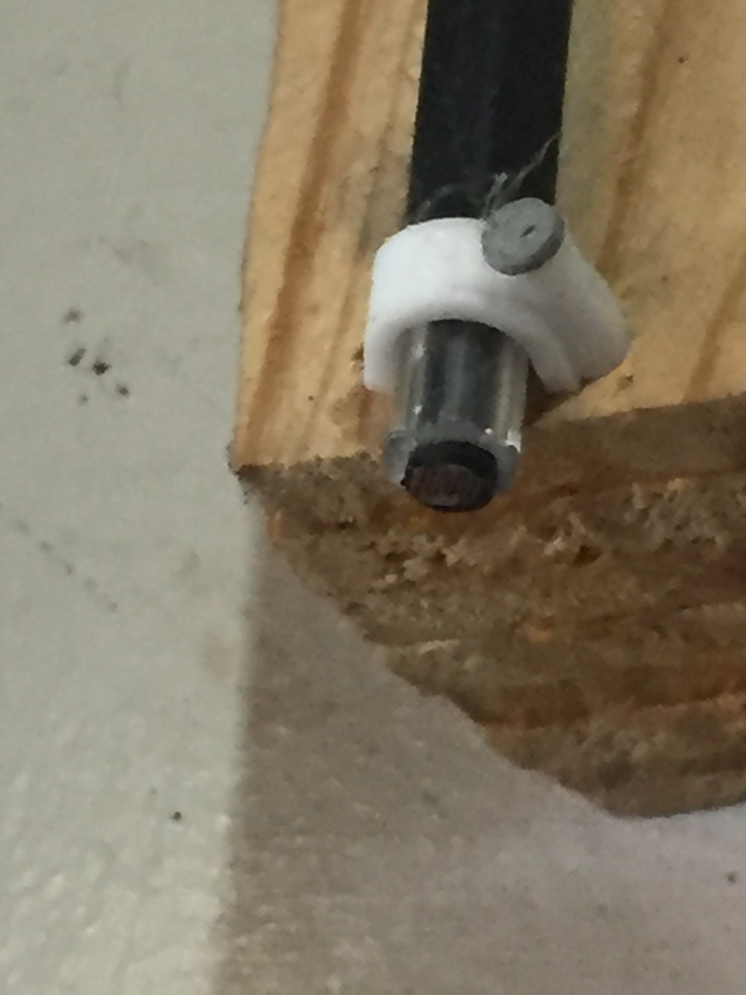
This is a close-up of the business end of the Light Sensor Assembly. You can see how the face of the sensor is left exposed.
The Electronics
In many ways, the electronics of this project paralleled the Open Door Sensor project. I retained the idea of a three-level Arduino / ProtoShield / XBee Shield sandwich. I also kept the idea of isolating Input electronics on the ProtoShield from Output electronics on the XBee Shield.
The Input Board
There were two substantive changes in the design philospophy of this board from the Door Sensor input board.
First, I decided to get rid of the connectors for input lines. Instead, I would solder a four-wire "tail" to the board that would lead outside the project box. I had decided that I would never disconnect this board from the outside world "inside" the box. Thus, there was no reason to have connectors.
Second, I decided I would no longer have a ground for each sensor leading "inside" the box. I would create a common ground for the input cabling "outside" of the box. This allowed the four-wire "tail" to be adequate for three sensors.
The Input Board (cont'd)
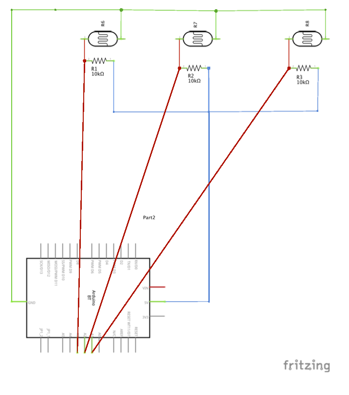
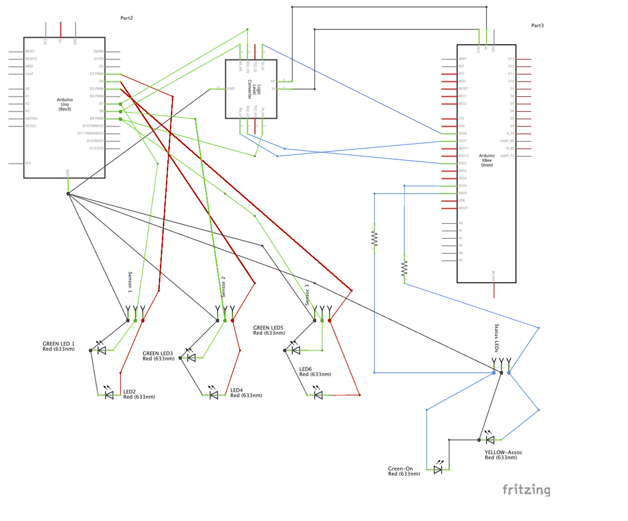
This is the schematic for the Light Sensor Input Board. The only real items of interest are the 10kΩ resistors. Each resistor serves as a voltage divider for connected sensor. The input signals are connected to analog input pins on the Arduino. The voltage divider circuitry reduces each sensor's input signal to a level where it can be handled by the analog input pins.
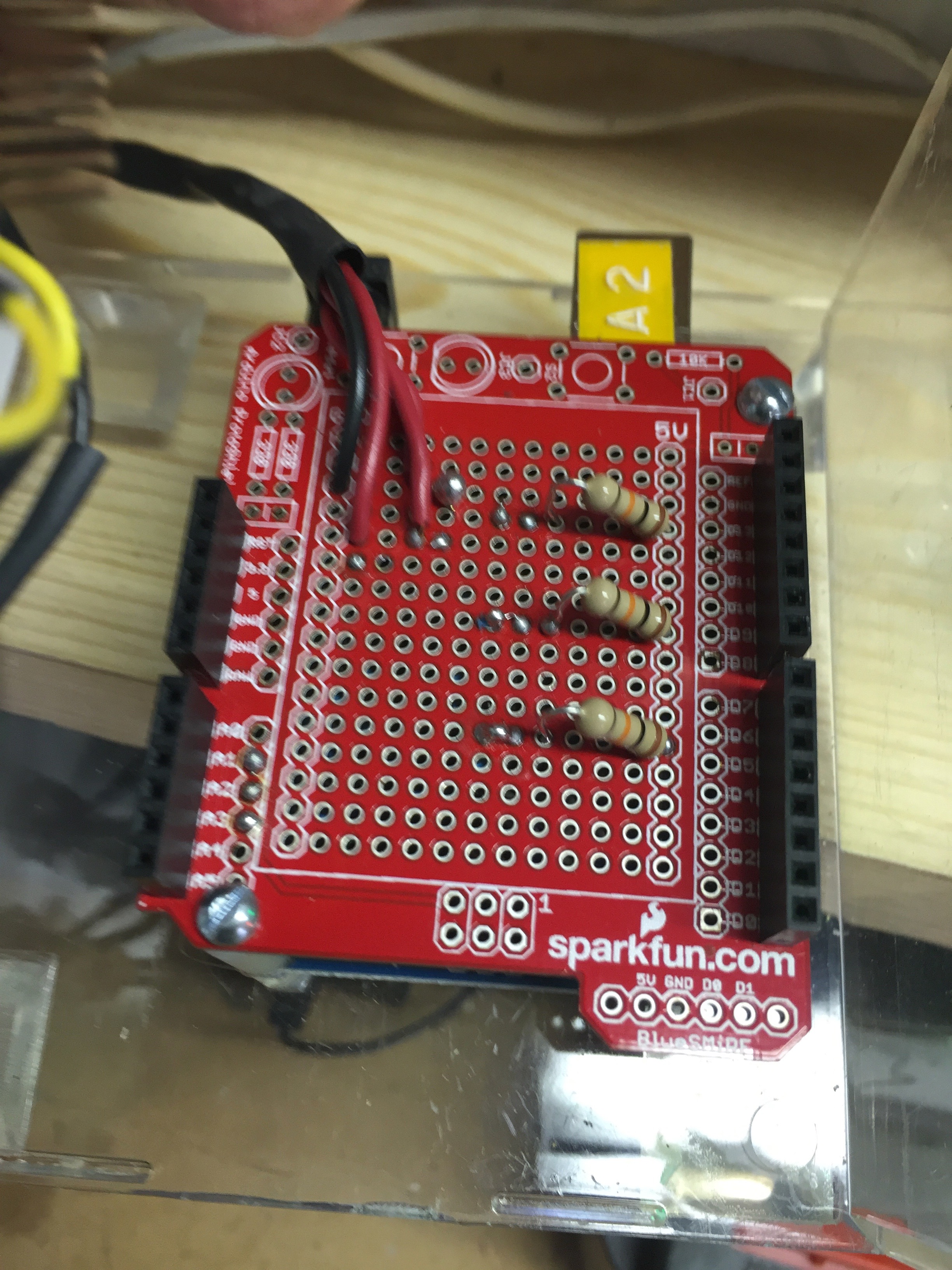
This is a picture of the completed Input Board. It really is as simple as it looks.
The ProtoShield was again sourced from SparkFun Electronics. The part number I used was DEV‑11665. SparkFun has since revised their shield and the current part number is DEV‑13819. The headers are tall stackable headers and each bank has two layers. The resistors are generic.
The Ouput Board
The Output Board underwent a major revision in this project. The Arduino operates at 5v. Signals sent from the Arduino pins are 5v signals. The XBee operates at 3.3v. The signals it receives on its input pins should be no more than 3.3v. In the Door Sensor project, I ignored this little inconsistency. I sent 5v Arduino signals directly to the XBee 3.3v input pins. For this project, I decided to address the issue.
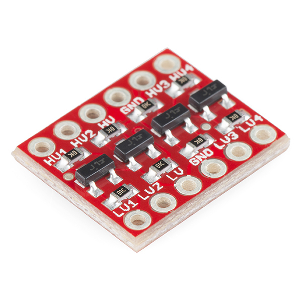
There are dozens of level-shifting circuits and components out there. I decided on the Sparkfun offering pictured here. The SparkFun bi-directional logic level converter safely steps down 5V signals to 3.3V AND steps up 3.3V to 5V at the same time. The part number is BOB-12009. (Note you have to add headers.)
The schematic for the Light Sensor Output Board is presented here. It shows how every signal between the Arduino and the XBee is routed through the Logic Level Converter. It also shows how Arduino signals to the LEDs are routed through JST connectors.
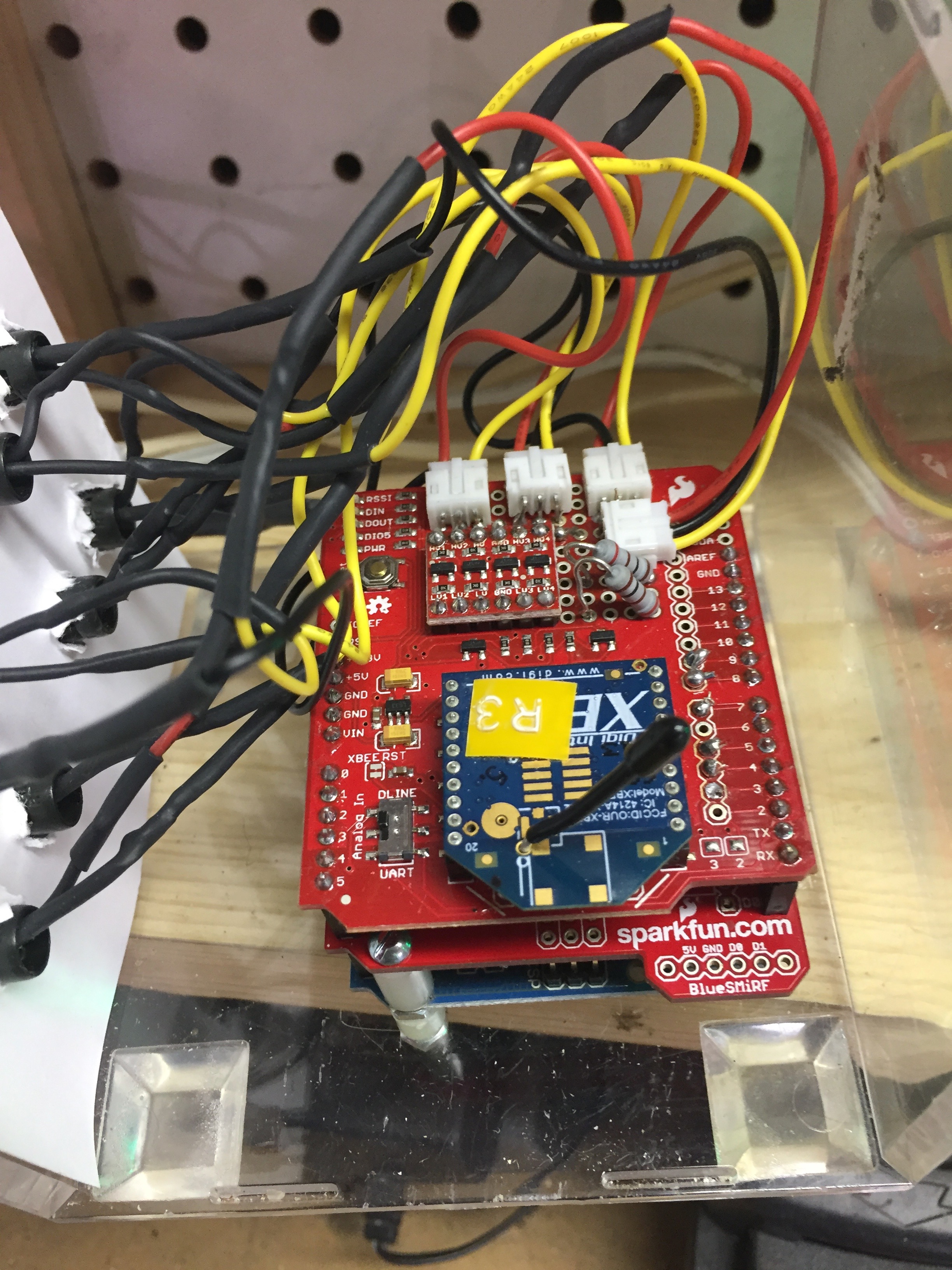
The use of JST connectors was retained from the redo of my Door Sensor Output board. They work slick. One three wire connector is attached to a pair of LEDs (one red, one green). The pair of LEDs share a common ground. You can see from this picture of the completed Output Board how much simpler the LED connections are. The XBee Shield was sourced from SparkFun Electronics and the part number is WRL-12847.
The extra resistors shown in both the schematic and the completed board photo are to protect the LEDs connected to the XBee's Associated pin and Power On pin. These are older LEDs and do not have embedded resistors.
Mechanical Notes
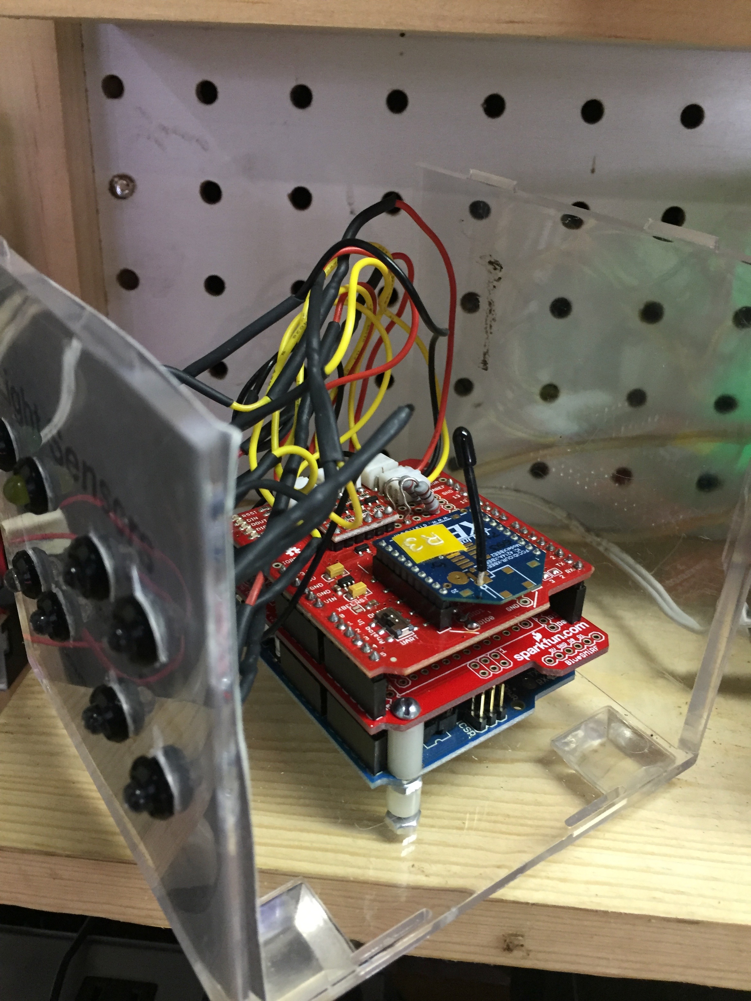
Pictured is the completed Light Sensor Ardino / XBee sandwich installed in the project box. A softball display cube was used as the project box as in the Door Sensor project.
Two lessons were learned from the Door Sensor project. First, I learned that the Arduino must be attached to the same piece of the cube as the front panel. This makes assembling and disassembling the device MUCH easier.
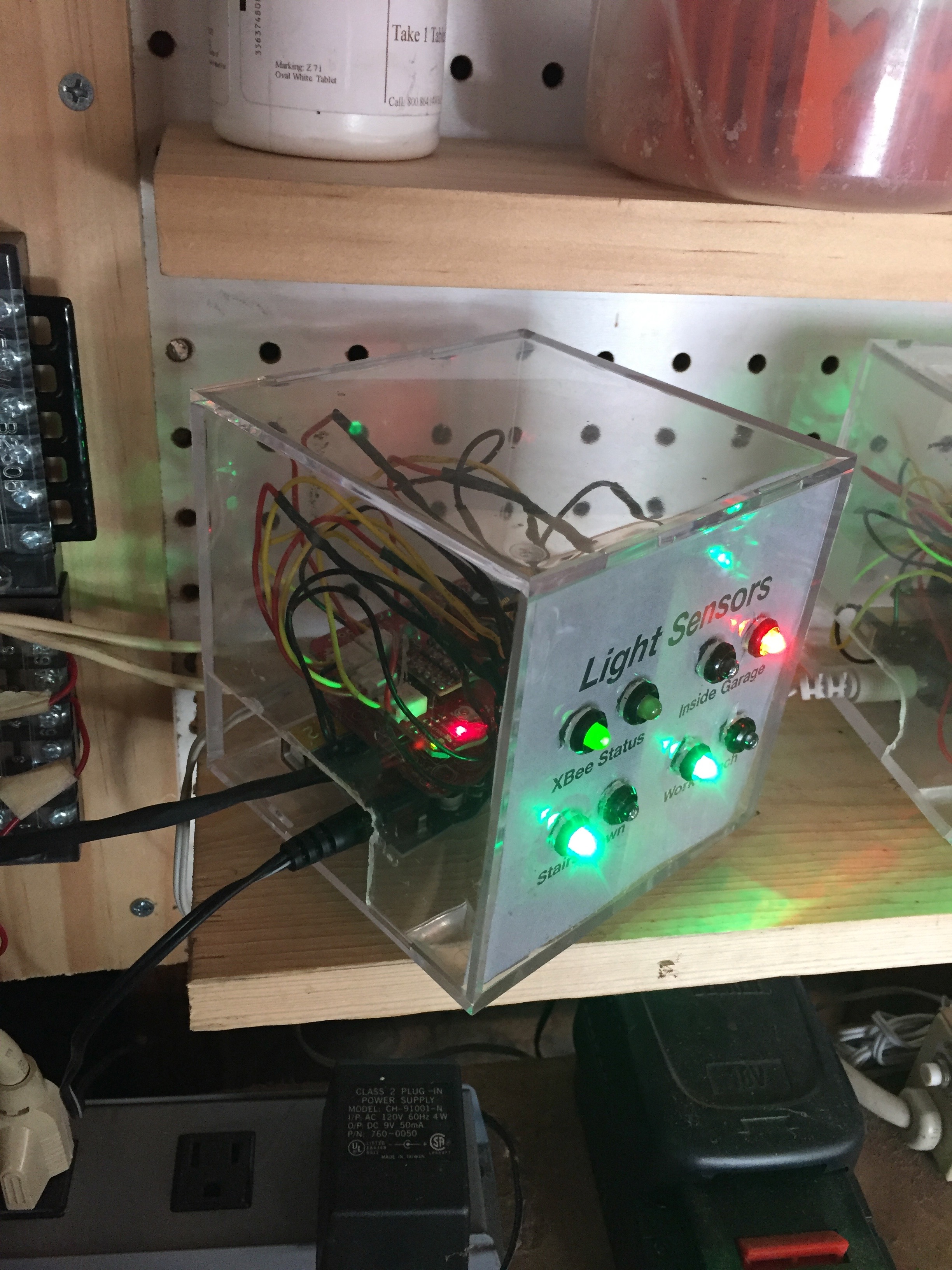
The second lesson was that I only needed one slot for the power jack, the USB port and the input "tail". In the Door Sensor project, I had cut slots on both sides of the cube.
This picture shows the Light Sensor device installed and operating "in the wild". It gives a clear view of the power cord and the input "tail" sharing one slot in the cube. This picture also gives one a better view of what the front panel looks like. Note there are far fewer nicks, cracks and scratches on this project box.
Software Notes
This section is intended to highlight unusual aspects of the Arduino software. The Processing-based software running on my iMac to display the status of all my sensors is described elsewhere.
The most important line of code in the Arduino sketch for this project is the declaration of a constant (array):
const int lightThreshold[] = {80,80,150};
The darker it gets, the greater the photocell's resistance becomes, and the lower the analog input voltage gets. The lower the analog input voltage gets, the lower the value reported by the Arduino's analogRead command becomes.
Some value between 0 and 1023 is the line where a light is considered on or off. The constant "lightThreshold" is the dividing line for the three sensors in the Arduino sketch. I determined these values by trial and error.
Open Issues
There are two issues related to the light / dark, thresholds explained in the paragraphs above. The on / off decisions made by the Arduino were mostly right... except:
1. During the middle of the summer, when the garage door is open, the level of ambient light in the garage causes the Arduino to report that the inside garage lights are on when they are not. I have tried to mitigate this phenomenon by "pointing" the light sensor assemblies directly at the light fixtures but that hasn't been enough. My next step is to attach a shrink tube baffle to the business end of the affected sensors in an attempt to further reduce the ambient light reaching the sensors. I don't think there is a software solution.
2. This past winter, i discovered the phenomenon that when it is very cold, the garage lights don't immediately reach their peak brightness when first turned on. The Arduino would report these lights off when in fact they were on. After a few minutes, the light bulbs warmed up, grew brighter, and the Arduino reported their state correctly. This is a software problem. The on / off thresholds are too high.
